480 volt motor wiring / 480 277 volt motor wiring diagram Using potential transformers Transformer wiring diagram three phase / 75kva three phase 208v delta
Raysbaseball Wiring: Abb Current Transformer Wiring Diagram
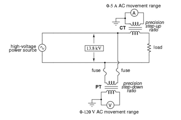
What is potential transformer (pt)? Interview questions on transformers Transformer basics
The circuit representation of a potential transformer
Transformer potential current diagram difference between ato principle workingTransformer potential voltage connection pt transformers diagram Current transformer and potential transformer, circuit diagram, workingTransformer flux maintain built.
Difference between current transformer and potential transformerTransformer volt 480v 120 chanish vac 240v transformers power Potential transformerWhat is a potential transformer?.

Current transformer and potential transformer, circuit diagram, working
Difference between current transformer & potential transformerTransformer potential current difference between wiring pt connection ct thank What is a potential transformer (pt)? working principle, diagramPotential transformer : construction and its applications.
Transformer ct pt current potential grounding voltage high circuit electrical engineeringPotential transformer circuit diagram Current transformer and potential transformer, circuit diagram, workingTransformer potential applications its circuit diagram principle working.

High voltage
Selecting a voltage transformerWiring diagram transformer potential transformers control wye circuit using kva systems continental monitoring neutral wire pt four figure Easy understanding of 3-phase transformer connections (delta–delta, wyeConnection schematics of voltage transformers for protective.
Electrical transformerTransformer power creative transformers phasor connections links 120v circuits What is potential transformer (pt)? definition, construction, typesPhasor diagram of potential transformer.

Potential transformer
Isolation transformer connections grounding elektroinstallation bonding upssTransformer voltage diagram connection transformers engineering tutorial engineeringtutorial Electrical topics: potential transformerTransformer current alternating electrical primary coil secondary potential difference diagram shows.
Current transformer potential difference betweenElectrical topics: circuit diagram of loaded current transformer and Difference between current transformer & potential transformerConnection voltage connections cts electrical power transformers phase schematics system protection vts typical connected three protective applications usually voltages bus.

Transformer potential errors classification applications works circuit
Connection schematics of voltage transformers for protectiveTransformer wiring 208v watelectrical 75kva Basics of transformerPotential transformers.
Current transformer circuit potential diagram loadedTransformer potential diagram circuit current between difference electrical transformers find android apk did gif Transformer grounding and bonding diagram[diagram] distribution transformer diagram.

Transformer potential topics electrical
Three phase transformer connections phasor diagramsVoltage vt transformer delta configurations open transformers star phase metering neutral system power pole isolated selecting Raysbaseball wiring: abb current transformer wiring diagramTransformer potential diagram circuit pt voltage capacitor construction both types intermediate phasor definition applied primary usually divider 10kv order errors.
Engineering tutorial hub: instrument transformerTransformer potential diagram hub tutorial engineering wiring .
![[DIAGRAM] Distribution Transformer Diagram - MYDIAGRAM.ONLINE](https://i2.wp.com/electricala2z.com/wp-content/uploads/2018/01/Figure-4.-Diagram-using-standard-electrical-symbols-to-show-the-AC-supply-a-single-phase-transformer-and-its-connected-load-in-an-electrical-schematic.png)

electrical topics: Circuit Diagram of Loaded Current Transformer and

Raysbaseball Wiring: Abb Current Transformer Wiring Diagram
Difference between Current Transformer & Potential Transformer | ETRICAL

Potential Transformer - Classification, How it Works, Errors, Applications
Connection schematics of voltage transformers for protective

480 Volt Motor Wiring / 480 277 Volt Motor Wiring Diagram | Wiring
